|
This article describes
the thought processes, and the construction of the Precision
Marine Bullet skimmer. I have been very fortunate to be involved
in this project, from its conception to the final production
models. Hobbyists need to see and understand what actually
goes into building a skimmer, and that is my reason for presenting
this report. The construction materials, testing, and final
optimization of the unit, adds up to a serious commitment
of time, effort, and money. I must thank the owner of Precision
Marine, Mike S. for his commitment to the project, for without
his expertise in constructing these skimmers, and providing
the raw material, this project would never have gone forward.
Evolution of a skimmer
Background
Back in August of '98, another avid hobbyist, James Wiseman,
and I had been discussing our fish tanks. In particular, we
had focused on the role of feeding large amounts of food in
a closed system.  One
concern that kept arising was how our tanks would
handle this nutrient load. The outcome of the discussion was
that if we wanted to feed heavily, we would have to find a
way to export the extra waste. One possible solution to this
problem is to eliminate the extra nutrients via skimming (foam
fractionation). Both of us had used traditional air-powered
or counter-current skimmers and were disappointed by their
lackluster performance. We thought a more efficient, large
water-processing skimmer might be a good solution. Within
a few days, James sketched a skimmer design outlining what
we thought was a good compromise of compactness, utility,
and performance. He had placed structural limits on the design
of this skimmer that were dictated by our large tanks. As
neither of us wanted an external skimmer, it had to fit under
a 30" cabinet. To save under-cabinet space, we wanted
the skimmer to reside in our sumps, which were less than 12"
wide. A third consideration was that it had to have high turnover
rates and water processing ability. Therefore, the skimmer
had to have a configuration that would allow for long contact
times, with fast and non-restricted flow-through. One
concern that kept arising was how our tanks would
handle this nutrient load. The outcome of the discussion was
that if we wanted to feed heavily, we would have to find a
way to export the extra waste. One possible solution to this
problem is to eliminate the extra nutrients via skimming (foam
fractionation). Both of us had used traditional air-powered
or counter-current skimmers and were disappointed by their
lackluster performance. We thought a more efficient, large
water-processing skimmer might be a good solution. Within
a few days, James sketched a skimmer design outlining what
we thought was a good compromise of compactness, utility,
and performance. He had placed structural limits on the design
of this skimmer that were dictated by our large tanks. As
neither of us wanted an external skimmer, it had to fit under
a 30" cabinet. To save under-cabinet space, we wanted
the skimmer to reside in our sumps, which were less than 12"
wide. A third consideration was that it had to have high turnover
rates and water processing ability. Therefore, the skimmer
had to have a configuration that would allow for long contact
times, with fast and non-restricted flow-through.
The
initial sketch outlined a step-shaped, tall rectangular box
that had a divider running down the center (Fig 1).
On the right side of the skimmer box was the water inlet where
the air/water mixture entered the chamber. This mixture would
run down the length of the right side to the bottom, where
a small baffle directed the mixture to the top of the left
side. On the top left side, we attached an interchangeable
neck and collection cup. The total height of this skimmer
was 18" on the right and 14" on the left. The skimmer
was 9" long and 4" wide. The total distance that
the processed water would travel was 28", which was equivalent
to a 28" tall reaction chamber if the skimmer was vertical.
This distance was more than sufficient for our purposes.
As an important aside, Chris
Paris, a Ph.D. student working on wastewater processing,
posted his ideas on how to increase the effectiveness of current
skimmer technology. In his writings, he presented complex
equations that described the fluctuating parameters that occur
in an air/water mixture when one increases the amount of air
mixed into a constant volume of water. Also, he discussed
parameters to increase contact time between an air bubble
and a waste molecule. The bottom line was that he presented
a strong argument for the use of more efficient aeration devices
(foam generators), as one way to create a skimmer with a high
waste removal capability. We found Chris Paris's proposal
of using the patented Beckett pond foaming head [See Explanation
Box Below] as a possible aeration device, very intriguing.
This was just the foam generator we needed for our new skimmer.
The Beckett valve possessed many favorable features such as
maximum air intake, extended water processing time and compact
size, which we could exploit in our design.
Once we had decided on using a Beckett head as an aerator,
the skimmer plans began to fall into place. Since neither
James nor I had much experience at working with acrylic or
building a skimmer, we decided to approach Mike at Precision
Marine. Mike is a long time local Houston resident and an
expert skimmer manufacturer. At the time, Precision Marine
had many airstone driven counter-current skimmers (the PM-AP
line), as well as recirculating counter-current traditional
venturi skimmers (the PM-CV-line). These skimmers, and his
product line, were well established in the aquarium trade.
We approached Mike with the idea of a new skimmer utilizing
the Beckett head, and presented him with our rough sketch
and our list of limitations. Once Mike was sold on the idea
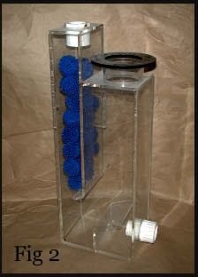
(thank God for margaritas), he constructed the first working
prototype based directly on James' sketch (Fig 2).
Mike's
first step in building our skimmer was to create a screw-on
containment chamber for the Beckett head (Fig 3). The
modular design allowed for two features: 1) we could mount
the Beckett head onto any of the test skimmers, and more importantly,
2) the containment chamber allowed a defined amount of air
to enter the Beckett head. From the literature and from Chris
Paris's writings, it was clear that a Beckett valve, which
was unrestricted to air, sucked in air at rates that were
detrimental to stable foam formation, since excess air resulted
in large bubble formation, and 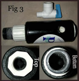 violent
water movement from the outlet. violent
water movement from the outlet.
As
a way to reduce bubble size ("tighten the bubbles"),
and provide a more consistent bubble output, we would have
to restrict the amount of air entering the Beckett head. One
way of restricting air is to create a surrounding (containment)
chamber, which has only 1 air opening (Fig3, top panel).
The top and bottom of the Beckett are sealed off to air, and
only allow water to pass through (Fig3, lower panels).
Air enters through a single side hole, in which a user-adjustable
needle valve is attached. This needle valve controls the amount
of air that enters the Beckett. This containment unit was
affectionately labeled the Beckett 'bullet', due to its rounded
shape (Fig 3). Once this containment chamber was built,
it was attached to the original skimmer, and our first working
prototype was tested.
Prototypes galore
As an initial test of the Beckett head (actually to prove
to ourselves that this was the best foaming head), we decided
to add the Beckett bullet on a skimmer system that we were
quite familiar with. We attached the Beckett bullet to a downdraft
skimmer; the downdraft design is a well-established skimmer
technology and works efficiently with ETS's patented spray
technology. In this first test, we sought to determine foaming
(aeration) quality, and to measure water flow. Since it was
unclear which pump would work the best with the Beckett bullet,
we tested the bullet/downdraft combination with both a Rio
3100 powerhead (900gph) and a Mak4 pump (1200gph). Our first
observation was that air intake was substantial, but with
obvious differences between the two pumps. With the low-pressure
pump (Rio3100), the bubbles were visibly bigger, there were
fewer bubbles (the water was grayish), and the water exiting
the bullet was violent. However, it did foam, but the foam
was interrupted and unstable. Using the high performance pump
(Mak4), we observed substantially better results. The bubbles
were smaller in comparison ("tighter"), the aerated
water was the color of milk (many more bubbles), and the water
leaving the exit tube was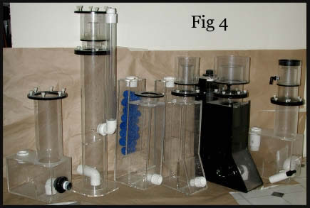 fast, but calm. Interestingly, tests using both pumps resulted
in foam formation within 10-30 minutes, but the foam climbed
higher and was denser using the Mak4 pump. Since this was
only a preliminary test, the Beckett bullet performed as good
as we had anticipated.
fast, but calm. Interestingly, tests using both pumps resulted
in foam formation within 10-30 minutes, but the foam climbed
higher and was denser using the Mak4 pump. Since this was
only a preliminary test, the Beckett bullet performed as good
as we had anticipated.
This is when things got interesting. Over the next weeks,
Mike built a few working models of the skimmer which we had
outlined for him. These prototypes (Fig 4) were tested
using the screw-on Beckett bullet powered by either the Rio
3100 pump or the Mak4 pump. Our first observations were, once
again, that pump pressure differences were significant. It
had become quite apparent that weak pumps would not make consistent
bubble size, and this resulted in "burping" of the
air/water mix. After we resolved the pump situation, the next
issue appeared: the Beckett head was so efficient at aerating
water, that air leaving the bullet rapidly expanded in the
entry chamber. This resulted in pressurizing the reaction
chamber and forcing all the water out. This problem was not
observed during the downdraft test, but to our dismay was
an inherent problem with our step-shaped reaction chamber.
Fortunately, there was an easy fix.
We focused on efficiently moving air through the skimmer,
and displaced the water baffle at the 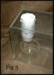 bottom
center of the reaction box. Displacing the center baffle forced
the air/water mix away from the downside, diverting it upward
towards the collection cup. This simple fix allowed for the
rapid passage of expanded air, and solved our pressurizing
problem. This new design resulted in the angular step-shaped
"Bigfoot" skimmer (Fig 4, 4th and 5th unit
from left). The Bigfoot skimmer was an excellent test model.
It was compact, contained over 30" of mixing distance,
and allowed air and water to rapidly move through it. However,
the curvature was not conducive to mass production of the
unit. {Author's note: I personally like the look}. Using the
information gleamed from the Bigfoot shape; we felt we were
one step closer to a final design. We learned that a displaced
baffle was required when using a direct injection scheme [see
explanation box below]. Furthermore, water diverted from
the baffle would foam directly adjacent to the water inlet.
Mike made 4 additional models (Fig 4, farthest right
unit) with differently shaped diverter baffles, such as circular
diverters. This circular diverter allowed for uniform spread
of the water mix (Fig 5). However, none of these uniquely
shaped diverters prevented "burping" or moving the
air/water mixture any more efficiently than the original displaced
baffle design. bottom
center of the reaction box. Displacing the center baffle forced
the air/water mix away from the downside, diverting it upward
towards the collection cup. This simple fix allowed for the
rapid passage of expanded air, and solved our pressurizing
problem. This new design resulted in the angular step-shaped
"Bigfoot" skimmer (Fig 4, 4th and 5th unit
from left). The Bigfoot skimmer was an excellent test model.
It was compact, contained over 30" of mixing distance,
and allowed air and water to rapidly move through it. However,
the curvature was not conducive to mass production of the
unit. {Author's note: I personally like the look}. Using the
information gleamed from the Bigfoot shape; we felt we were
one step closer to a final design. We learned that a displaced
baffle was required when using a direct injection scheme [see
explanation box below]. Furthermore, water diverted from
the baffle would foam directly adjacent to the water inlet.
Mike made 4 additional models (Fig 4, farthest right
unit) with differently shaped diverter baffles, such as circular
diverters. This circular diverter allowed for uniform spread
of the water mix (Fig 5). However, none of these uniquely
shaped diverters prevented "burping" or moving the
air/water mixture any more efficiently than the original displaced
baffle design.
The Final Shape Arrives
The box-shaped mixing chamber was a natural evolution of the
Bigfoot's curves, but without the requirement for elaborate
shapes, which created problems for the mass production of
the unit. 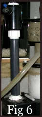 Next,
we required an area where the foam would accumulate and stabilize.
Mike incorporated a clear cast acrylic reaction column, 6"
tall by 6" wide, to replace the collection side of the
Bigfoot. However, incorporating this column required the reaction
box to be wider than we had hoped. Next,
we required an area where the foam would accumulate and stabilize.
Mike incorporated a clear cast acrylic reaction column, 6"
tall by 6" wide, to replace the collection side of the
Bigfoot. However, incorporating this column required the reaction
box to be wider than we had hoped.
The final box measured 6" wide and
10" long. The inlet side where the Beckett bullet was
attached was removed, and replaced by a single piece of PVC
(Fig 6). The reaction column was fitted with a threaded
flange, which permitted multiple sizes and shapes of collection
cups to attach onto it. This final skimmer fulfilled our initial
design criteria. It was compact, it would fit sideways into
a 12" wide tank, and the total height was 24", including
a 10" tall collection cup with the restrictor neck. Finally,
after 12 prototypes, we had a final design. However, the skimmer
was not complete without finalizing the perfect neck size,
collection cup setup, and exhaust port. The exhaust port is
critical in determining the volume of escaping air, in so
much as an inadequately sized exhaust port may exert backpressure
in the skimmer, reducing its efficiency. Unfortunately, the
determination of the collection cup size and the exhaust port
diameter was done empirically.
Mike constructed a series
of necks and cups with varying heights, widths, and exhaust
port sizes (Fig 7). Then, each neck was added to a
test skimmer, and monitored to determine airflow, the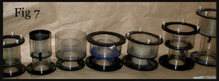 neck's ability to support and produce dry foam,and the ability
to project this foam over the neck. The final design was a
compromise between sufficient airflow through the skimmer,
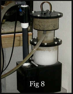
and our height limitations. The first working models were
built in ABS plastic and were tested on both of our tanks
(Fig 8). As a test of each configuration's water processing
ability, we measured and compared the volume of water going
into the skimmer, versus the volume of water exiting the skimmer.
Utilizing a Mak4 pump to power the Beckett bullet, we measured
approximately 1200gph in and 500gph out. As a point of reference
for comparison, we used a Mak4 pump to drive an MTC HSA1000
skimmer (another Beckett head skimmer), and noted it had an
output of 450gph.
neck's ability to support and produce dry foam,and the ability
to project this foam over the neck. The final design was a
compromise between sufficient airflow through the skimmer,
and our height limitations. The first working models were
built in ABS plastic and were tested on both of our tanks
(Fig 8). As a test of each configuration's water processing
ability, we measured and compared the volume of water going
into the skimmer, versus the volume of water exiting the skimmer.
Utilizing a Mak4 pump to power the Beckett bullet, we measured
approximately 1200gph in and 500gph out. As a point of reference
for comparison, we used a Mak4 pump to drive an MTC HSA1000
skimmer (another Beckett head skimmer), and noted it had an
output of 450gph.
|
How
does it work?
Why a Beckett head?
The Beckett 1408 pond foaming aeration head (Diagram
1A, top panel): The background on this head is well
described in the literature and its application for
aerating fish and farm ponds is well established. For
the purpose of this article, I will briefly describe
its background and offer a short description of how
it works. This 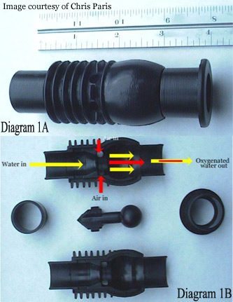 information
will play an important role in the design of the skimmer
and its utility in a home skimmer. Background: This
plastic (or metal) aeration head was designed to disrupt
surface tension on farm and fishponds allowing for highly
oxygenated water. It accomplishes this by mixing tremendous
amounts of air into pumped water. This air/water mix
is then sprayed into the air as a fountainhead. information
will play an important role in the design of the skimmer
and its utility in a home skimmer. Background: This
plastic (or metal) aeration head was designed to disrupt
surface tension on farm and fishponds allowing for highly
oxygenated water. It accomplishes this by mixing tremendous
amounts of air into pumped water. This air/water mix
is then sprayed into the air as a fountainhead.
The Beckett head was a novel design and a radical interpretation/modification
of a traditional venturi valve (Diagram 2). The familiar
traditional venturi valve has a single air intake (called
a pitot tube). Essentially, pressurized water enters
the injector inlet, it is constricted (by passing through
a restriction) toward the injection chamber and changes
into a high-velocity jet stream. The increase in velocity
through the injection chamber results in a decrease
in pressure in the injector body. When a sufficient
pressure difference exists between the inlet and outlet
ports of the injector, a vacuum is created inside the
injector body, which initiates suction through the suction
port. At this point air is literally sucked into the
vacuum space. As the jet stream is diffused toward the
injector outlet, its velocity is reduced and it is reconverted
into pressure energy (but at a pressure lower than injector
inlet pressure), and the "microbubbles" are
produced. In comparison, a Beckett head is a circular
3D version of a traditional venturi (Diagram 1B,
bottom panel). The designer of the Beckett utilized
the same concept of forcing water through a restriction.
However, in this application, the restriction is located
right before a large three-dimensional ball. A spike-
shaped divider evenly restricts the water stream over
the ball, and focuses the water under the four air intakes,
evenly spaced at ninety degrees apart. Water traveling
past the spike and around the ball, results in air being
drawn in from the four intakes. Once past the ball,
the air/water mix rapidly expands and creates microbubbles.
However, in comparison to the traditional venturi, the
Beckett head amplifies the amount of air drawn in. Due
to the design of the valve, we observed a significant
increase in the amount of bubbles created. Additionally,
the size of the bubbles appeared much smaller than what
we observed while using a traditional venturi valve.
Argos Catalogue
includes a wide range of electronics such as TVs and Smartphones.
If I have explained this adequately, you should understand
that bubble generation from the Beckett head is solely
dependent on the force of water through it: the stronger
the push (i.e., pump pressure) through the Beckett,
the more consistent the water stream flows over the
mixing ball. Faster water movement through the Beckett
head results in increased air intake and smaller bubble
formation, so a combination of a strong and powerful
pump will provide the best end result.
Beckett heads are designed for use in an end-terminal
application. As  described
above, Beckett valves were designed to sit on the end
of a PVC pipe and have water forced through them like
a fountain. These valves do not withstand the backpressure
of being under water, and consequently, for the most
efficient air intake, there should not be any backpressure
on the outflow of the head. This also provides an indication
as to how we can best utilize the Beckett to maximize
air intake. Maximum air intake and performance can be
obtained by placing the air intakes of the Beckett head
at a level which is higher than the water level in the
skimmer. Elevating the Beckett head on a small piece
of PVC will often achieve this result. described
above, Beckett valves were designed to sit on the end
of a PVC pipe and have water forced through them like
a fountain. These valves do not withstand the backpressure
of being under water, and consequently, for the most
efficient air intake, there should not be any backpressure
on the outflow of the head. This also provides an indication
as to how we can best utilize the Beckett to maximize
air intake. Maximum air intake and performance can be
obtained by placing the air intakes of the Beckett head
at a level which is higher than the water level in the
skimmer. Elevating the Beckett head on a small piece
of PVC will often achieve this result.
Tangential injection or direct
injection
Tangential injection (Diagram 3 left side) allows
the air/water mix to be injected at a tangent (angle)
into the reaction chamber. The most common tangential
injection method is to inject from or near the bottom,
facing up toward the inside wall of the reaction chamber.
This results in a beneficial swirling effect that effectively
increases contact time. The most important benefit of
using tangential injection is that  lower
performance pumps can be used to drive the Beckett head.
This is due to the fact that bubble inconsistencies
do not directly affect water in the reaction chamber,
as these bubbles are gently spilled into the reaction
chamber. Skimmers that utilize this injection method
are: the Precision Marine BulletXL, Marine Technical
Concepts (MTC) HSA250, and the Aerofoamer skimmers. lower
performance pumps can be used to drive the Beckett head.
This is due to the fact that bubble inconsistencies
do not directly affect water in the reaction chamber,
as these bubbles are gently spilled into the reaction
chamber. Skimmers that utilize this injection method
are: the Precision Marine BulletXL, Marine Technical
Concepts (MTC) HSA250, and the Aerofoamer skimmers.
The main benefit of direct injection (Diagram 3,
right side) is that it allows for a shorter reaction
chamber. However, this injection method also requires
a strong water pump, as foam formation in the water
column can be disrupted by bubble inconsistencies and
"burping". A skimmer which uses this direct
injection technique is the Bullet skimmer. Another directly
injected skimmer is the MTC HSA1000. In its design,
the manufacturer has decided to lengthen the reaction
chamber by utilizing a long downflow tube; the outflow
of water is then diverted upward, which essentially
doubles its reaction chamber length.
|
Image Legend
Fig 1. Cartoon
of James Wiseman's sketch. 1)-water inlet; 2)-"downside"
area of initial air/water mixing; 3)- mixing area "reaction
area"; 4)- water diverter baffle; 5)-drain outlet; 6)-"upside"
collection side where foam coalesces and stabilizes; 7)-interchangeable
collection cup and neck.
Fig 2.
A working prototype of the skimmer taken from James' sketch.
Fig 3.
The "Bullet" containment chamber. Top panel: this
is a completed containment chamber. Shown is the user adjustable
air valve (white/blue) the Bullet chamber with single air
intake hole. The bottom of the chamber faces left, and has
a 1' screw thread. The water inlet (top of the Bullet) faces
right. Lower panels: Left side, looking down into a Beckett
Bullet (note the spike divider and its four diverters); Right
side, looking up into the bottom of the Bullet (note the rounded
surface of the ball).
Fig 4.
A few of the skimmer prototypes. Note that all skimmers have
a 1" screw-on adapter on the inlet (to attach the Beckett
Bullet) and a universal flange with screw threads on the collection
side which allows a quick interchange of any sized collection
cup and neck.
Fig 5.
Circular diverter.
Fig 6. A
line up of different sized and shaped collection cups with
restriction necks.
Fig 7. The
down tube. Note that the Beckett Bullet threads onto the top.
Fig 8. The
finished product, a working Bullet2 prototype.
|