|
Following is an overview/assembly list and user review of a new GEO 818 calcium reactor. I have no affiliation with GEO and offer this information as educational and informational material for potential buyers.
Overview
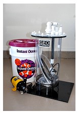
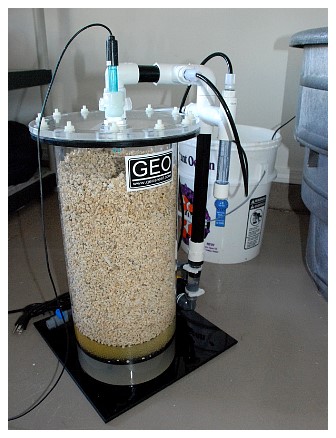
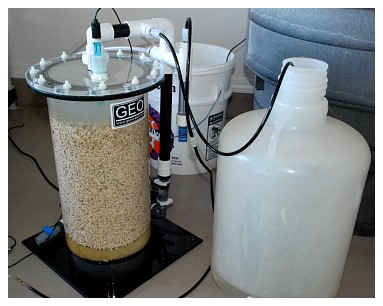
Unfortunately, I did not get to see the boxes in which the reactor was shipped. The reactor was purchased from a local fish store, where it was inspected prior to my picking it up. The reactor came in a single reinforced cardboard box with all the tubes and instructions contained inside the skimmer’s body (Figure 1). The pump (a Pan World unit) came in a separate Styrofoam box.
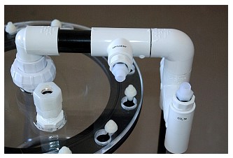
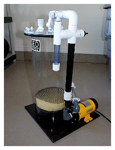
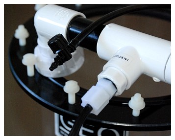
Figure 1 (left). The GEO 818 as supplied from the manufacturer, including the reactor body and Pan World pump. The salt bucket is shown for scale. Figure 2 (right). The lid, showing white bolts and the union for the pump return and pH probe socket.
|
My first impression of the reactor was that it was huge. The model name “818” refers to its dimensions, which are 8” in diameter and 18” tall. A close inspection of the unit showed that it looks very nicely put together, with no glue spills, rough edges or acrylic burrs. The lid is clamped down and the body contains all of the pipes and fittings (Figure 2). The pump is not attached. One thing that immediately stood out was that the ports on the reactor were labeled with their function, such as CO2 inlet, feed and effluent. This is a nice touch; simple, but extremely useful. The main body is made from clear acrylic tubing sitting on a black acrylic plate. The pump’s feed connection is supplied pre-fitted to the reactor’s body with a Uniseal®. The top is a black flange glued to the acrylic tube, and the lid is a clear acrylic disk fitted with a union (for the pump return) and a pH probe port (Figure 2). The lid is held down by 12 white plastic bolts that slot into the keyhole-cut top plate. Removing the plate involves turning each nut a few turns, twisting the lid slightly and removing it.
Assembly
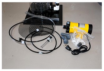
The unit’s total assembly took approximately 30 minutes. After slackening the retaining nuts around the head of the unit, all of the pipes and paperwork were removed. The instructions for assembly are somewhat poor; however, the unit is very simple to assemble even without the help of detailed instructions. After removing the chamber’s contents it is clear that there are multiple hoses, fittings and clamps (Figure 3).
Figure 3. The reactors contents, removed from the body.
|
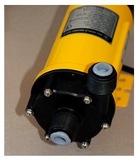
Figure 4. The grey plugs need to be removed from the pump.
|
The first step was to assemble the pump and its connections. Each opening in the pump was capped with a grey plug. These were removed and Teflon tape was applied to the screw threads (Figure 4). The two grey threaded elbow/pipe nipples were screwed to the intake and the return. The pump was aligned by placing it onto the base so that the pump’s base plate lined up with the holes in the black acrylic, and the two fittings were adjusted so that the outflow faced the reactor’s base and the inflow (front of pump) pointed straight up (Figure 5). With the pump in place, the distance between the two pipe nipples at the reactor’s feed was measured, and a piece of the supplied plastic hose was cut to size. This was moistened and slid onto the reactor end-first, taking care not to stress the unit. Holding the tube to prevent stress, the pump nipple was slid into the tube and adjusted so that the pump’s base plate was located over the holes in the black acrylic base (Figure 6).
 |
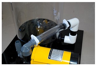 |
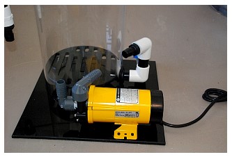
Figure 5. Alignment of the pump and reactor feed prior to cutting and fitting the clear tubing.
|
Figure 6. The clear tubing is fitted; first to the reactor, then to the pump, and clamped down using the supplied fittings.
|
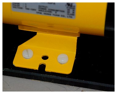
Once fitted, the pump can be screwed down to the base plate using the four white plastic screws and washers (Figure 7). Performing the assembly in this order saves undue stress on the reactor’s body at the Uniseal/feed connector. The next step was to align the pump’s intake to the reactor. The reactor’s top was placed back over the screws and gently fixed down. The union at the top was loosened to allow the down pipe to rotate until it lined up over the pump’s intake, and the distance between the pump and the reactor’s nipples was measured (Figure 8).
Figure 7 (left). After fitting the lower tubing, the pump is affixed to the base with the four plastic screws. Figure 8 (right). The top is refitted, the union opened and the down pipe aligned with the pumps intake to measure the length of pipe needed.
|
The hose was cut to size and slid onto the pump’s intake, the reactor’s down pipe was released from the reactor by opening the union, and then the nipple was seated into the tube until the union fit flushly. This prevents stressing the white plastic pump mounting screws. Once seated, the union was checked and closed to ensure a tight seal. The supplied white plastic cable clips were placed around each nipple/pipe connection.
After the pump was fitted, the reactor feed was assembled. This is comprised of a length of clear plastic tubing with a black reducer at one end connected to a larger bore pipe. This latter piece of pipe allows the user to slide a MaxiJet powerhead into the end to act as a feed pump (I use a MaxiJet 400). The connections between these two pipes are pre-sealed with cable clips, which I found this to be a great feature of this product. In the past I have assembled reactors only to be left hunting for fittings that allow a connection to a feed pump. This assembly required only tightening the pre-fitted white screw to the inlet on the reactor that is marked as “feed.” The effluent was similarly fitted, and comes supplied with a flow regulator tap - again a nice feature (Figure 9).
Figure 9. Assembly of the effluent showing the flow restrictor.
|
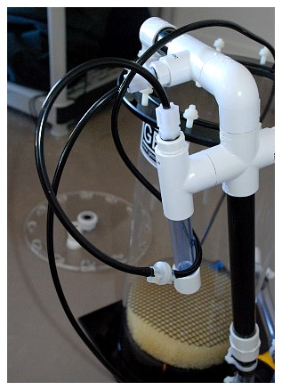
The CO2 feed is a length of black CO2-safe pipe and includes a one-way valve to prevent back pressure from forcing water into the CO2 regulator/solenoid assembly. This is assembled as described above into the reactor’s fitting labeled “CO2”. Although this reactor has a self-filling bubble chamber, I added some RO/DI water to the chamber prior to fitting the CO2 feed (Figure 10).
Figure 10. Assembly of the CO2 feed showing the one-way valve.
|
Figure 11. The sponge foam insert is added and CaribSeas media is used to fill to the line on the GEO label. The lid is then refitted.
|
The final assembly steps were fitting the pH probe and preparing and filling the media chamber. I recommend, because of the unit’s weight, that this part be performed in the unit's final resting place. Once filled, it is quite heavy and may be damaged by attempts to move it.
|
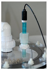
Figure 12. The pH port is a nice addition and allows continuous monitoring of the chambers pH. |
The reactor comes with two pre-cut plastic mesh sheets that fit at the base of the media chamber over the diffuser plate. These prevent large media from falling through. I prefer using small media, however, so I had to make a media trap out of foam. This was a simple task to perform (because I had foam and/or a suitable filter pad), but it would have been nice if this option had been included with the unit. Using the black mesh as a template, a foam disk was cut and slid down over the diffuser plate, and two precut mesh sheets were laid on top of it. For media I use CaribSea’s brand crushed coral, and it took 25-30 lbs. to fill this model to the line on the GEO label (see Figure 11). The media were pre-washed prior to adding them. Once filled, the top flange was cleaned of any media residue, the O ring was checked for seating and the top was fitted. The screws should be tightened in an alternating pattern to ensure proper seating, and each requires just hand tightness to create the seal. The last step was inserting the pH probe. The top of the reactor contains a port into which the probe can be inserted. Once inside, the nut should be tightened down, compressing an O ring onto the probe side and sealing the unit (Figure 12). I have monitored the effluent’s pH on previous reactors. The inclusion of a port for measuring the contents' pH increases the unit's sensitivity and is an excellent feature of the reactor. Finally, the top union was closed and the reactor was ready.
Use
My previous experience with reactors and plumbing, in general, suggested that a water test for leaks would be prudent, and this was performed. The reactor was fed with a MaxiJet 400 unit using fresh RO/DI water. As the water level rose, the reactor was systematically checked for leaks. When none was found, the reactor was filled until water exited the effluent pipe. Knowing that the media would remain cloudy, I used separate buckets to feed and collect water, rather than recirculating it, so that the media’s dust could be removed (Figure 13). The recirculating pump was turned on after confirming that the unit was leak-free. Bubbles immediately churned through the system and then settled. My impression was that the pump was very quiet. The water inside the reactor became quite cloudy from the churned bubbles and the media dust. I also noticed that bubbles were drawn in through the bubble trap/CO2 feed. This was remedied by blocking the free end of the black CO2 pipe. After the unit had been running for an hour, the CO2 feed was connected to the solenoid of the CO2 regulator/tank, the feed pump was placed into the sump, the return pipe cable was tied to the side of the sump to prevent it from moving and the unit allowed to recirculate tank water.
 |
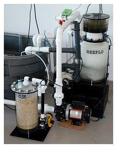 |
Figure 13. The reactor is flushed to remove residual dust prior to final installation.
|
Figure 14. The reactor is installed and connected to CO2 and the pH controller.
|
While the unit flushed with tank water I began the process of setting up the peripheral equipment. My system uses a Milwaukee SM122 pH monitor connected to the solenoid/regulator assembly of a 20 lb. CO2 bottle (Figure 14). When setting up a reactor I try to ensure the system's safety as much as possible. A pH controller is an essential piece of equipment, in my opinion. These operate very simply by reading the pH in the chamber (or in the effluent) and if it is above a preset level (I use pH 6.6), they activate the solenoid and release CO2 gas into the system. Once the pH drops to the desired level, the controller turns off the CO2 feed. Trying to operate a calcium reactor without the automated ability to monitor and control pH is a recipe for disaster. It can be done, but I don’t advise it.
When setting up a reactor it is important to know your current calcium and alkalinity levels. A calcium reactor’s function is to stabilize the system, not to increase calcium or alkalinity, so knowledge of the current conditions is essential. Because I was swapping out one reactor for another, my levels were reasonably good and needed no adjustment.
The first step in getting the reactor working is regulating its water feed. Large tanks need a higher flow through a given reactor than small tanks. Determining the actual flow through the system requires a little effort and time to figure out, as described below. The best way to do this is to start with a flow of 1-2 liters per hour through the system. Fortunately for me, I needed a large flow so I left the control valves fully open. The effluent end of the pipework was arranged so that it entered my sump in an area of high water flow/turbulence. This helped blow off any excess CO2 in the effluent and mix the high alkalinity and calcium contents of the effluent.
The pH probe was connected to the controller and the dial on the front was set to pH 6.6. The needle valve on the regulator at the solenoid was closed and the solenoid was connected to the controller's controlled electrical outlet. As the connection is made the solenoid might, depending on the type, “click” audibly as it opens. The pH controller will also flash to indicate that it is operating. To test this, the controller was turned off, and it should also click as it turns off. With power restored, the needle valve was slowly opened, resulting in CO2 bubbles forming in the bubble counter. I initially allow a high flow of bubbles - in the range of 100 bubbles/min - into the unit to rapidly acidify the water. As these dissolve the pH begins to drop. I initially shoot for a drop in pH of around 0.1 units per minute. If it is falling faster, I decrease the bubbles; if slower, I increase them. As the pH drops to 7 the bubble count is further decreased to slow the drop in pH. I try to get the final drop from pH 7 to 6.6 to proceed at around 0.1 pH units every five minutes or so. This final bubble count is close to that actually needed to run the reactor.
The reactor is now running. Following a final inspection of the unit for leaks, it was allowed to run for several hours, during which time the tank was monitored. It is unlikely that there will be any issues with pH swings in the tank, unless the original Ca and Alk levels are extremely low. In this case the tank's ability to buffer the incoming low pH water is decreased, so the reactor's flow needs to be set lower than described above, or else a two-part buffer needs to be used to bring the levels into an optimum range. After several hours the effluent can be tested to see if it is, indeed, adding Alk and Ca to the water.
Fine Tuning
As the reactor runs, the CO2 feed opens and closes as the pH rises and falls. I try to adjust these on/off periods to make the CO2 feed as constant as possible (i.e., regulate the bubble flow such that the reactor is virtually always getting the minimum CO2 it needs to keep the pH at 6.6). Closing the needle valve down slightly lengthens the “bubbles on” period. Paying time and attention at this point reduces the pH swings in the reactor, so the minimum amount of CO2 will be required. This is important because the effluent then will always contain the least possible amount of dissolved CO2. The alternative is short pulses of CO2 into the system and a rapid pH drop, which results in periods of a high amount of CO2 entering the tank, which may affect the tank’s water stability. Setting the needle valve in this fashion also helps to prevent an accidental acidification of the tank’s water, should the solenoid stick open, because it is almost always open anyway. When using this method, the solenoid can be periodically checked by turning the pH controller off for a few seconds.
After several days the tank’s calcium and alkalinity levels should be measured and compared to their original values. If the values are the same, the reactor’s water flow needs no modifications. If the Alk and Ca levels have dropped, the flow needs to be increased by a small amount. If the Ca and Alk levels have dropped by 10%, increase the flow by approximately 10%. Likewise, if they have increased, decrease the flow. Be aware that if the flow increases, then the bubble count will require an increase as well to keep up with the demand. Similarly, a decrease in flow will require fewer bubbles.
This last process is repeated until the Ca and Alk levels have stabilized. After that, a good quality two-part solution should be used to gradually raise calcium and alkalinity to optimal levels for your system. The reactor should not be used to increase these levels because it can very easily drive them beyond optimal values, creating imbalances and, potentially, tank crashes. Setting the reactor to run as described above helps to prevent such issues. All that is left to do is to monitor the tank, and check the reactor for flow and the controller to ensure that it is working correctly.
Using this method kept the initial flow through my unit in the range of three liters per hour, with a final bubble count dialed to about 50 bubbles/minute. Satisfied that the unit was running, I left it on and just checked it for leaks every couple of hours. After 24 hours I checked the effluent's calcium and alkalinity levels. Ten milliliters of effluent was collected and added to 90 mls of fresh RO/DI water. Salifert test kits were used. Correcting for the 10-fold dilution factor, the effluent's dKH was around 30, and its calcium level was around 900-1000. Because my Ca and Alk levels in the system were good, I monitored the tank every week to ensure stability. I did not have to significantly alter the flow through the reactor to set it for my system.
Concerns/Issues
The only issue I have experienced with this unit is that it has a tendency to suck air into the system if the water feed is decreased. This became apparent when I was re-working an area of my sump and turned the water flow off. Within a few minutes bubbles were appearing in the media from air being drawn in and circulated. Unlike CO2, air does not dissolve rapidly in water, so it accumulates. As it circulates, it bumps the media and clouds the water. This stops when full flow is restored, and the media rapidly clear as the air is expelled. Because air is being drawn in, the fault lies in the suction part of the system, which is the area from the reactor’s top to the pump’s intake. This is likely due to a poor fitting, such as the white plastic hose clips supplied with the reactor or the Teflon tape around the intake pipe’s nipple. Because I run my reactor fully open, this is not an issue for me, and I haven’t tried to locate the point where air is being sucked in. I mention this only because I have seen other GEO reactors with the Pan World pump do this - presumably due to this pump's high power.
Long-term Use
I have now been running this reactor for four months. During this time I have had no issues or concerns other than the one detailed above. Calcium and alkalinity levels have remained stable, and my corals are growing extremely well. The media have dissolved sufficiently that a top-off is required. I estimate that 1/2 - 2/3 of the CaribSea crushed coral has dissolved already, which equates to approximately 10 lbs. in four months. The unit remains almost silent and leak-free.
Overall
This is a very nice looking and extremely efficient unit. The pump is silent and the fact that all of the pipes, valves and plumbing are supplied makes this unit extremely attractive. Its rapid assembly and ease of use are also pluses. On the down side, it would be nice to have larger heads on the white fittings at the lid. Opening and closing them is somewhat awkward, but not sufficiently difficult to make me change them. The fact that they will be opened and closed only every six months or so makes them tolerable. The lack of a sponge for small filter media was a surprise, because all other fittings are supplied. Another improvement that could be made would be more specific instructions for the unit’s assembly.
Marks Out of 10
A solid 9.0! Adding a sponge and better instructions would bring this unit very close to a 10. It is, however, a great value for the money. It’s nicely built and very robust.
|